|
|
Holographic Human-Computer Interface EMR Interaction EMR allows two or more holograms to interact with each other directly in the H2CI, rather than through interaction with a command object, as in Passive Tracking. However, the interaction could be supplemented with Passive Tracking. For example, holograms might be set not to interact until they were within a threshold distance of each other, requiring that a command object move one or more holograms to within the threshold distance of one or more other holograms. Direct interaction would be automated through deterministic algortihms, including stochastic processes, or artificial intelligence. Military simulations and virtural reality games are among the many applications.
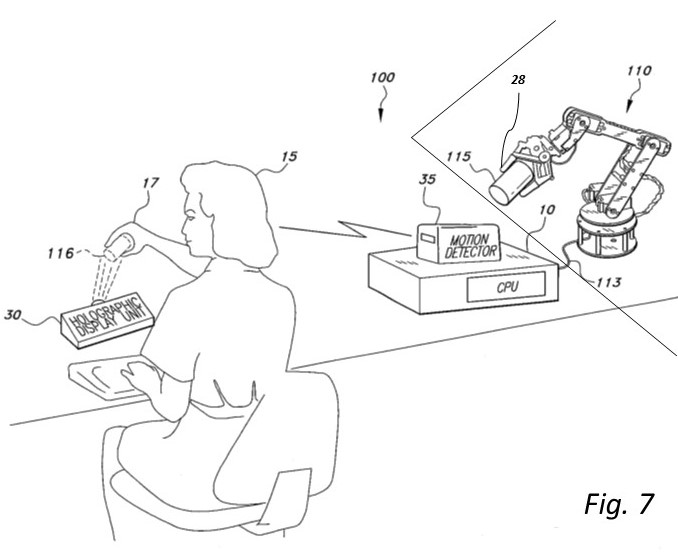
Because the command object could emit and detect EMR, for purposes of conveying and detecting information among displayed holographic objects, and/or the command object, independently of the motion detector, detecting and emitting EMR would be a form of sensor feedback. Displayed holographic objects (both targets and instruments or tools) would emit and detect EMR to and from each other for purposes of conveying and detecting information among displayed holographic objects. Such emitted information might, for example, reflect the physical characteristics of the physical object represented by a displayed hologram, possibly for virtual targets too large for the motion detector setup, which could be detected by virtual controls (FIG. 9). Emission and detection of EMR would also support haptic feedback and virtual reality applications. FIG. 9 is an environmental, perspective view of an embodiment of the H2CI showing virtual representations of physical controls, sensors for proximity of physical objects to each other, and virtual objects emitting and detecting EMR. Virtual Control 60 is in communication with Physical Control 120, the physical control for an external system. Virtual Target 50 represents Physical Target 115. As the physical command object 17 moves the Virtual Control 60 toward any part of the Virtual Target 50, the Physical Control 120 moves the external system toward that same part of the Physical Target 115 (i.e., direct control). CPU 10 and Holographic Display Unit 30 enable the virtual Control 60 to detect EMR 26 from the virtual Target 50 and virtual Target 50 to emit previously coded and stored EMR 26. This EMR describes details of the Physical Target 115 to the external system via sensor 28 on Physical Control 120. In the case of a Physical Control for a robotic external system (e.g., 110 in FIG. 7), these details could describe to the external system how much pressure to apply in manipulating the Physical Target 115.
The hands serve as the command object 17 so that the motion detector 35 or emission and detection of EMR 26 (Fig. 9) will detect the user’s conventional movements with respect to the holographically represented physical object 116 (e.g., the cup or a control). Haptic feedback would allow the user to detect that contact was made with the virtual control. The CPU 10 can be programmed to only interpret clockwise or counter-clockwise rotational movement of the user’s hands, e.g., for turning a wheel, and only transmit a control signal when such motion is detected by the motion detector 35 or emission and detection of EMR. This discrimination is done under computer control (CPU 10), automatically, in realtime, without human intervention. That is, the type of motion (intended motions specific to the control or unintended general motions to be ignored) is tracked by the motion detector 35 or emission and detection of EMR 26 and interpreted by the CPU 10. Another applicaton of the H2CI would be holographic representations of the results from robotic resequencing equipment connected to components equivalent to 30 and 35, or EMR 26 in lieu of 35. This could be two-way—holographic sequencing components could be used with virtual controls to analyze the holographic genome for further sequencing using EMR emission and detection. In addition, holographic display of genomes would be useful in analyzing the structure as well as the function of the genome. Nuclear power plants also could apply the realism of the H2CI. When a component in a nuclear power plant is detected to be outside normal parameters it must be dealt with immediately. As was discovered with Three Mile Island, when one component fails it may start a cascade of failing components. Interpreting the multiple alerts may require more time than is safe for prioritizing and responding, as happened with Three Mile Island. Displaying holograms of failing components, including their physical location relative to each other, with audio, textual, and/or visual cues to indicate priority and corrective action, alleviates the problem. In current displays, displaying such complex information requires multiple flat screens and limits an integrated display of the failing components with related cues and actions easily comprehended by operators. Operators using such an integrated interactive holographic display are able to respond by touching the displayed hologram as indicated by the cue provided by the shape of the hologram of the failing component (e.g., the component itself or a Virtual Control representing a lever or a wheel). Haptic feedback using EMR with the Virtual Control could be used to confirm the touch. In the nuclear power plant application, Virtual Controls may be displayed for each failing component to allow the operators to take corrective action using the familiar controls for the component. This means that properly interpreting the touch (i.e., type of motion) is crucial, so that unintended touches (motions) are distinguished under computer control, automatically, in realtime, without human intervention. The hologram of the failing component (as represented by 50 in FIG. 9) may be displayed in its actual size or scaled for convenience, including controls (levers, buttons, wheels, or replicas of physical flat screen displays as represented by 60 in FIG. 9) used for controlling the physical component. |
||
|
Overview | Benefits and Applications | Passive Tracking | Relationship| Patent Description and Claims |Technology |Site Map | Contact Information Copyright © 2011 |


